Within IR Glare
Why Bright Infrared Targets Can Look Too Large
Optical spreading and clipping can make a distant hot source appear wider than the object producing it.
On this page
- How optical spreading enlarges a bright source
- Why clipped cores hide the true boundary
- When pixel width overstates physical size
Page outline Jump by section
Introduction
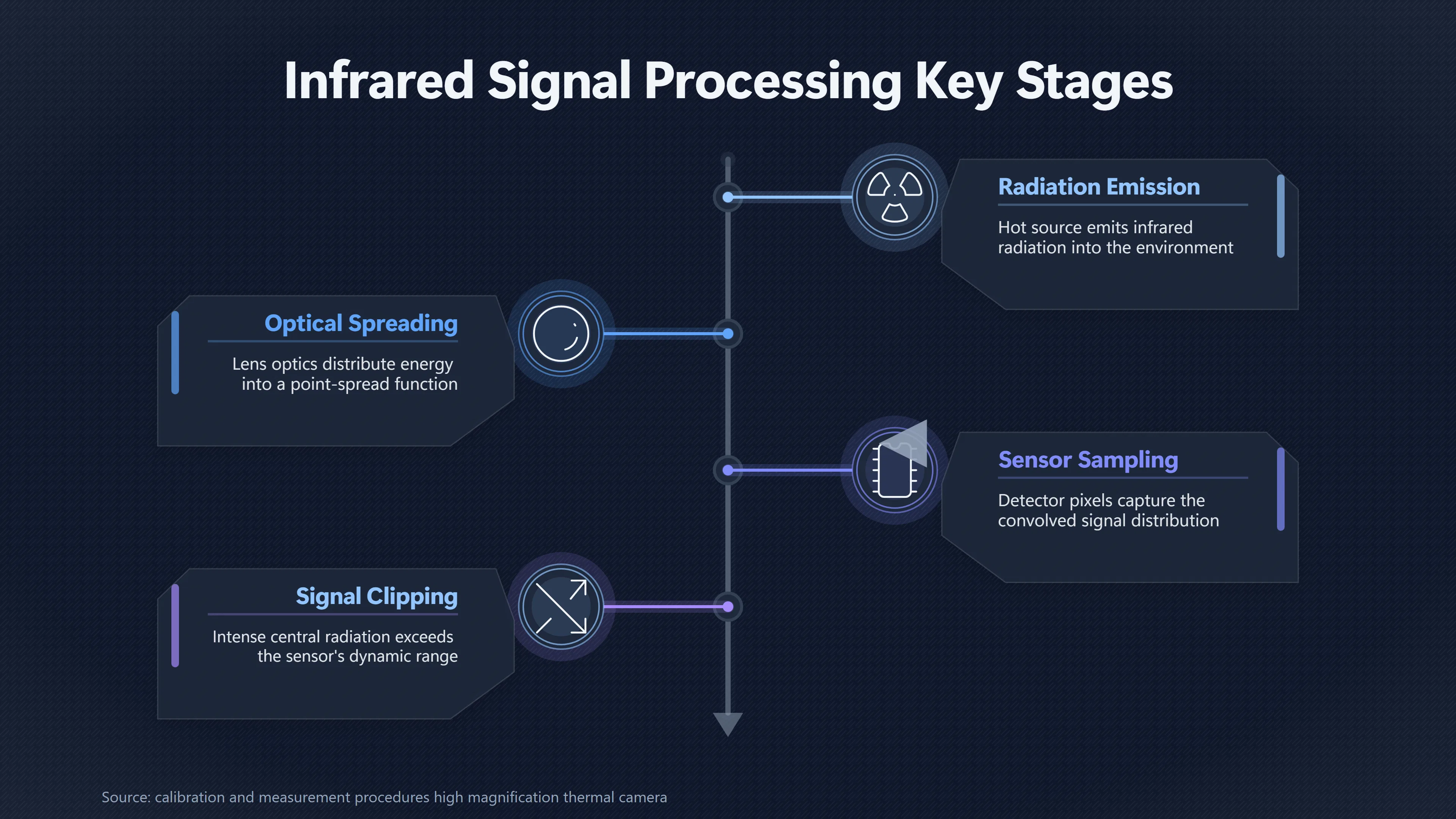
A bright infrared target can occupy more pixels in an image than its physical outline would justify. The key reason is that an infrared camera does not map each point on a distant object to one perfectly confined detector point. Its optics spread radiation into a point-spread function (PSF), while detector sampling, stray light and subsequent processing determine which parts of that spread remain visible. For a strong source, more of the PSF’s outer signal can rise above the displayed or detectable threshold, making the bright patch look wider.[NIST]nist.govcalibration and measurement procedures high magnification thermal cameraCalibration and Measurement Procedures for a High Magnification Thermal Camera | NISTJanuary 8, 2016…
If the centre also reaches the sensor’s or processing chain’s limit, saturation or clipping removes information precisely where the source is brightest. The result can be a conspicuous, apparently solid infrared blob whose displayed edge is not the object’s physical edge. This matters when assessing UFO or UAP imagery: counting the pixels across such a blob and treating them as a literal silhouette can substantially overstate what the camera has actually resolved.
How optical spreading enlarges a bright source
The fundamental effect begins before saturation. Every real imaging system blurs spatial detail to some degree. Its PSF describes what the camera records when presented with an ideally tiny point source: rather than appearing in one infinitesimal location, the source’s energy is distributed over a central region and surrounding wings. NIST treats the PSF as an important source of uncertainty in infrared thermography, while its work on spatial stray light likewise describes unwanted radiation spreading between image locations in terms of the instrument’s PSF.[NIST]nist.govcalibration and measurement procedures high magnification thermal cameraCalibration and Measurement Procedures for a High Magnification Thermal Camera | NISTJanuary 8, 2016…
That spreading matters especially when a target is small compared with the camera’s angular resolution. Imagine a distant hot engine whose true image would cover roughly one detector pixel in ideal geometrical optics. The actual infrared signal may contribute to several neighbouring pixels because of diffraction, aberrations, focus, scattering and detector sampling. The camera therefore records the response of the target convolved with the imaging system, rather than a direct geometrical tracing of the target boundary. A point source itself is consequently recorded over an area rather than as a point.[GNU]gnu.orgPSF (GNU Astronomy UtilitiesPSF (GNU Astronomy Utilities)…
Brightness changes how much of that distribution is conspicuous. The underlying principle is familiar from diffraction imaging: brighter unresolved sources can appear larger because progressively weaker portions of their spread pattern exceed the detection or display threshold. The geometrical source has not grown; a larger fraction of the camera’s response to it has simply become visible. This is why point-like stars can acquire apparently different diameters according to brightness even though their apparent discs are generated by the imaging system rather than their resolved physical surfaces.[Wikipedia]WikipediaAiry diskAiry disk
Infrared observations provide particularly useful demonstrations because hot sources can have enormous contrast against their surroundings. Infrared astronomy routinely has to model extended PSF wings around bright objects: Spitzer measurements, for example, can recover information from the unsaturated PSF wings even when a bright star’s central region is heavily saturated. That is direct evidence of the distinction crucial here — radiation belonging to an unresolved source remains recorded well outside its saturated centre.[arXiv]arxiv.orgAccurate Photometry of Saturated Stars Using the Point-Spread-Function Wing Technique with SpitzerNovember 19, 2021…
For a distant aircraft, this means that the hottest component can dominate the apparent dimensions of the infrared target. A compact engine or exhaust region does not need to be physically as broad as the bright patch seen on screen. If the aircraft itself is only marginally resolved, the spreading from its strongest infrared components can overlap the weaker signal from the fuselage, wings and tail, leaving an enlarged luminous or dark blob instead of an obvious aeroplane shape.
Why clipped cores hide the true boundary
Optical spreading and saturation are different phenomena, although they can occur together. Optical spreading distributes a source’s radiation spatially. Saturation occurs when part of the imaging system can no longer represent an increasing input normally. Teledyne FLIR explicitly notes that sufficiently intense radiation can exceed a thermal imager’s saturation limit and recommends attenuating the incoming signal when imaging scenes beyond the camera’s usable range.[FLIR Customer Support]flir.custhelp.comFLIR Customer Support FLIR CamerasFLIR Customer SupportFLIR Cameras - Saturation Limit of a Thermal ImagerOctober 7, 2024…
Once the central pixels saturate, differences within the brightest part of the source can disappear. Several genuinely different radiance values may all be rendered at, or close to, the same maximum output level. In a displayed image this can produce a broad white region in white-hot polarity, or its dark equivalent when the polarity is reversed. The resulting plateau should not be interpreted as a uniformly emitting physical surface. It may simply be the part of the recorded signal that has reached the available ceiling.
The wider imaging world makes the geometry of this failure mode especially clear. NASA describes CCD blooming as occurring when a bright source overloads pixels and charge spills into neighbouring pixels; the Kepler telescope consequently records fine extensions from some saturated stars. NASA’s TESS documentation similarly explains that charge exceeding a pixel’s full-well capacity can spill into adjacent pixels. The precise detector architecture and artefact need not be the same in every military or thermal infrared camera, but these examples demonstrate the broader warning: once an imaging detector is driven beyond its normal range, the dimensions of the saturated region are not a dependable measurement of source dimensions.[NASA]nasa.govKepler's First LightKepler's First Light - NASAApril 8, 2009…
Clipping creates an additional interpretive problem because it destroys information that might otherwise help locate the real boundary. Consider a compact hot source with a steep intensity peak surrounded by weaker PSF wings. With adequate dynamic range, an analyst can examine the entire intensity profile. If the centre is clipped, however, the true height and shape of that peak are unknown. Only the flattened core and surviving outer signal remain.
This is why saturated-source analysis in astronomy can deliberately use PSF wings rather than the core. Research using Spitzer demonstrated accurate photometry of heavily saturated stars from their unsaturated PSF wings. The technique works precisely because saturation makes the centre unsuitable for ordinary intensity measurement while the surrounding optical response still carries information about the source.[arXiv]arxiv.orgAccurate Photometry of Saturated Stars Using the Point-Spread-Function Wing Technique with SpitzerNovember 19, 2021…
For UAP interpretation, the practical lesson is narrower but important: a clean-looking outer edge around a clipped infrared patch is not automatically the edge of a craft. It can instead mark where the combination of PSF intensity, background level and display mapping finally falls below the threshold needed to remain conspicuous.
When pixel width overstates physical size
A common mistake is to measure an infrared blob as, say, 12 pixels wide and assume those 12 pixels directly represent the object’s angular width. That inference is safest only when the target is sufficiently resolved and the imaging response is understood. Thermal-camera manufacturers themselves distinguish between merely detecting a target in a pixel and having enough pixels on it for reliable measurement. FLIR notes that real optics require a target to cover more than a single instantaneous field of view (IFOV), and gives a commonly used guideline of roughly three times the IFOV to account for optical aberrations in measurement applications.[FLIR]flir.comTemperature Guns Versus Thermal Imaging Technology | FlirTemperature Guns Versus Thermal Imaging Technology | Flir
Experimental thermal-imaging research reaches the same general conclusion from another direction. A study of the size-of-source effect found that measurement errors depend strongly on target size, distance and the number of pixels exposed to target radiation. It recommended substantially more target coverage than a single pixel for accurate radiometric work. Although size-of-source error concerns temperature measurement rather than UAP identification, it demonstrates an important physical fact: radiation recorded in a thermal-camera pixel is not necessarily isolated to a neat geometrical patch corresponding exactly to that pixel’s nominal field of view.[MDPI]mdpi.comEvaluation of the Size-of-Source Effect in Thermal Imaging CamerasEvaluation of the Size-of-Source Effect in Thermal Imaging Cameras
Distance makes this distinction increasingly important. If an aircraft becomes small enough that its identifying structures fall below, or close to, the system’s spatial resolution, its physical angular size continues to shrink with range but its image cannot shrink indefinitely into a perfectly geometrical miniature. It increasingly approaches the camera’s response to an unresolved source. The observed width is then governed by a mixture of true target extent and PSF width rather than by target extent alone.
This creates three useful regimes:
- Well resolved: many independent resolution elements span the target. Wings, fuselage and other structures can influence the measured outline, so pixel dimensions have a meaningful relationship to physical dimensions.
- Marginally resolved: target size and PSF width are comparable. The recorded outline is a blend of real structure and optical spreading, making direct size estimates increasingly model-dependent.
- Effectively unresolved: the target is smaller than the detail the system can reliably reproduce. Its displayed dimensions mostly describe the imaging system’s response to its infrared emission, not a resolved physical silhouette.
Digital enlargement does not solve the last two cases. FLIR explicitly notes that merely seeing a target, or enlarging it digitally, does not mean that sufficient detector pixels were originally placed on it for accurate measurement. Digital zoom can make existing pixels easier to inspect, but it cannot recreate spatial information the optics and detector never resolved.[FLIR]flir.comHow Far Can You Measure with a Thermal Camera? | FlirHow Far Can You Measure with a Thermal Camera? | Flir
Why brightness makes size estimates especially fragile
The most counter-intuitive part of the mechanism is that apparent width can change even when the physical object’s angular dimensions do not.
Suppose the camera response to a compact source has a bright centre and progressively fainter wings. If the background or display threshold is relatively high, perhaps only the centre is distinguishable and the source looks narrow. Increase the source’s infrared radiance and the entire response rises. Regions farther into the PSF wings now become visible, so the displayed patch grows. No physical expansion is required.
The same reasoning explains why an apparent boundary defined by a contrast threshold is not invariant. Changing gain, contrast stretch, polarity, background temperature or processing can move the displayed edge inward or outward. What looks like a sharply bounded object to the viewer may actually be a contour in the camera’s intensity distribution.
NIST’s work on spatial stray light underscores why high-contrast scenes are especially vulnerable. It reports that spatial stray-light effects can be significant enough that characterising and correcting the PSF substantially reduces measurement errors, specifically noting applications involving images with high contrast ratios.[NIST]nist.govStray light correction | NISTStray light correction | NIST…
A bright infrared target against cold sky or cloud therefore presents almost the ideal conditions for confusing signal extent with object extent. The visually dominant pixels answer the question “where is this target’s infrared signal conspicuous in this processed frame?” They do not necessarily answer “where does the solid object begin and end?”
What this means for UFO and UAP footage
The relevance to UFO and UAP reports is not that every ambiguous infrared blob must be glare from an aircraft. The mechanism is valuable because it establishes something more limited and testable: the apparent dimensions of a bright, poorly resolved infrared target cannot safely be treated as its physical dimensions without accounting for the imaging system.
This issue has featured prominently in discussion of the 2015 Navy “Gimbal” footage, where one proposed interpretation is that part of the conspicuous infrared form is glare associated with a conventional aircraft viewed at long range. Public analyses disagree about the event’s geometry and interpretation, so the footage does not by itself establish how much of its visible form is optical spreading. The general optical mechanism, however, does not depend on resolving that particular case. Infrared PSFs, saturation and spatial spreading are established properties of imaging systems.[Metabunk]metabunk.orgThe Shape and Size of Glare Around Bright Lights or IR Heat Sources | MetabunkThe Shape and Size of Glare Around Bright Lights or IR Heat Sources | Metabunk
Recent official UAP releases also reinforce the need to describe infrared detections cautiously. The All-domain Anomaly Resolution Office (AARO) commonly refers to ambiguous features in infrared footage as areas of contrast, rather than automatically identifying the displayed patch with a physical silhouette. That terminology is appropriate because a sensor image first establishes a radiometric contrast pattern; determining the dimensions and identity of the underlying object requires additional information.[AARO]aaro.milOpen source on aaro.mil.
For analysts, a pixel-count size estimate is therefore most persuasive when several conditions can be demonstrated together: the range is constrained; the instantaneous field of view and optical configuration are known; the target spans enough genuine resolution elements; the signal is not clipped; the PSF is characterised or demonstrably small compared with the target; and the apparent boundary remains stable under sensible changes in display processing.
Without those safeguards, a bright infrared patch should be treated as an upper-envelope image of where detectable radiation has spread, not automatically as a ruler laid across the underlying object.
The key distinction
The central lesson is simple but easy to miss when an infrared image looks visually crisp: pixel width is not necessarily object width.
A distant hot target is filtered through the camera’s point-spread function before it becomes an image. Brightness can make progressively weaker portions of that spread visible, spatial stray light can extend high-contrast signals, and saturation can erase the intensity structure of the centre. Meanwhile, inadequate target sampling means that apparently precise pixel measurements may exceed the amount of physical detail the camera actually resolved.[NIST]nist.govcalibration and measurement procedures high magnification thermal cameraCalibration and Measurement Procedures for a High Magnification Thermal Camera | NISTJanuary 8, 2016…
Consequently, an ordinary compact heat source can produce an infrared patch that is smoother, wider and less structurally informative than the object responsible for it. In UFO and UAP footage, that makes apparent infrared size useful evidence only when the sensor’s resolution, dynamic range and optical response are accounted for. A large bright blob can be a large object — but it can also be a much smaller object’s radiation spread across the imaging system.
Amazon book picks
Further Reading
Books and field guides related to Why Bright Infrared Targets Can Look Too Large. Use these as the next step if you want deeper reading beyond the article.
Introduction to Infrared and Electro-Optical Systems
This newly revised and updated edition offers a current and complete introduction to the analysis and design of Electro-Optical (EO) imag...
Infrared Detectors and Systems
Infrared Detectors and Systems offers a deep and detailed examination of the optical detection process and the electronics of mimicking t...
Infrared Thermal Imaging: Fundamentals, Research and Applicat...
This richly illustrated hands-on guide is designed for researchers, teachers and practitioners. The huge selection of examples taken from...
eBay marketplace picks
Marketplace Samples
Live-tested eBay searches with available results related to this page.
Selected fromUFO poster oneBay.co.uk.



Current eBay listing
I Want To Believe UFO Poster Giclée Fine Art Heavyweight Print

Current eBay listing
VINTAGE UFO FLYING SAUCERS COMIC ADVERTISING A2 POSTER PRINT
Endnotes
1.
Source: nist.gov
Title: calibration and measurement procedures high magnification thermal camera
Link:https://www.nist.gov/publications/calibration-and-measurement-procedures-high-magnification-thermal-camera
Source snippet
Calibration and Measurement Procedures for a High Magnification Thermal Camera | NISTJanuary 8, 2016...
Published: January 8, 2016
2.
Source: nist.gov
Title: Stray light correction | NIST
Link:https://www.nist.gov/pml/sensor-science/optical-radiation/stray-light-correction
Source snippet
Stray light correction | NIST...
3.
Source: nist.gov
Link:https://www.nist.gov/publications/effects-emissitivity-and-camera-point-spread-function-temperature-measurement-segmented
Source snippet
The Effects of Emissitivity and Camera Point-Spread Function on the Temperature Measurement of Segmented Chip Formation Using Infrare...
4.
Source: gnu.org
Title: PSF (GNU Astronomy Utilities)
Link:https://www.gnu.org/software/gnuastro/manual/html_node/PSF.html
Source snippet
PSF (GNU Astronomy Utilities)...
5.
Source: nist.gov
Title: Characterization and Correction of Stray Light in Optical Instruments | NIST
Link:https://www.nist.gov/publications/characterization-and-correction-stray-light-optical-instruments
Source snippet
Characterization and Correction of Stray Light in Optical Instruments | NIST...
6.
Source: Wikipedia
Title: Airy disk
Link:https://en.wikipedia.org/wiki/Airy_disk
7.
Source: arxiv.org
Link:https://arxiv.org/abs/2111.10054
Source snippet
Accurate Photometry of Saturated Stars Using the Point-Spread-Function Wing Technique with SpitzerNovember 19, 2021...
Published: November 19, 2021
8.
Source: nasa.gov
Title: Kepler’s First Light
Link:https://www.nasa.gov/?p=409867
Source snippet
Kepler's First Light - NASAApril 8, 2009...
Published: April 8, 2009
9.
Source: heasarc.gsfc.nasa.gov
Title: HEASARCTESS Telescope Information
Link:https://heasarc.gsfc.nasa.gov/docs/tess/telescope_information.html
10.
Source: flir.com
Title: Temperature Guns Versus Thermal Imaging Technology | Flir
Link:https://www.flir.com/en-gb/discover/rd-science/temperature-guns-versus-thermal-imaging-technology/
11.
Source: mdpi.com
Title: Evaluation of the Size-of-Source Effect in Thermal Imaging Cameras
Link:https://www.mdpi.com/1424-8220/21/2/607
12.
Source: flir.com
Title: How Far Can You Measure with a Thermal Camera? | Flir
Link:https://www.flir.com/discover/professional-tools/how-far-can-you-measure-with-a-thermal-camera/
13.
Source: metabunk.org
Title: The Shape and Size of Glare Around Bright Lights or IR Heat Sources | Metabunk
Link:https://www.metabunk.org/threads/the-shape-and-size-of-glare-around-bright-lights-or-ir-heat-sources.10596/
14.
Source: arxiv.org
Link:https://arxiv.org/abs/2306.08773
15.
Source: aaro.mil
Link:https://www.aaro.mil/Next-AARO-Home-redesign/Next-Parent/Next-UAP-Report-Documents/poster/dividLink/
16.
Source: science.nasa.gov
Title: wfi technical
Link:https://science.nasa.gov/mission/roman-space-telescope/wfi-technical/
17.
Source: aqua.nasa.gov
Link:https://aqua.nasa.gov/content/airs
18.
Source: aaro.mil
Link:https://www.aaro.mil/Next-AARO-Home-redesign/Next-Parent/Next-AARO-UAP-Imagery-Acc-Table/
19.
Source: oem.flir.com
Link:https://www.oem.flir.com/en-150/learn/discover/a-guide-on-cost-effective-thermal-lens-integration-what-to-know-for-defense-and-autonomous-vehicle-applications/
20.
Source: aaro.mil
Link:https://www.aaro.mil/Next-AARO-Home-redesign/Next-Parent/Presidential-UAP-Transparency-Initiative/
21.
Source: aaro.mil
Link:https://www.aaro.mil/Next-AARO-Home-redesign/Next-Parent/Presidential-UAP-Transparency-Initiative/dvpmoduleid/77396/
22.
Source: science.nasa.gov
Title: how to measure the size of an asteroid
Link:https://science.nasa.gov/photojournal/how-to-measure-the-size-of-an-asteroid/
23.
Source: science.nasa.gov
Title: ultra low noise infrared detectors for exoplanet imaging
Link:https://science.nasa.gov/science-research/science-enabling-technology/technology-highlights/ultra-low-noise-infrared-detectors-for-exoplanet-imaging/
24.
Source: nist.gov
Link:https://www.nist.gov/publications/linnik-point-spread-functions-time-reversed-logarithmic-diffusion-equations-and-blind
25.
Source: aaro.mil
Link:https://www.aaro.mil/Next-AARO-Home-redesign/Next-Parent/Presidential-UAP-Transparency-Initiative/videoid/1006159/dvpcc/false/
26.
Source: mdpi.com
Link:https://www.mdpi.com/1424-8220/24/20/6662
27.
Source: aaro.mil
Link:https://www.aaro.mil/Next-AARO-Home-redesign/Next-Parent/Presidential-UAP-Transparency-Initiative/videoid/1006078/dvpcc/false/
28.
Source: mdpi.com
Link:https://www.mdpi.com/1424-8220/24/16/5152
29.
Source: ntrs.nasa.gov
Link:https://ntrs.nasa.gov/citations/20240002367
30.
Source: aaro.mil
Link:https://www.aaro.mil/Next-AARO-Home-redesign/Next-Parent/Presidential-UAP-Transparency-Initiative/videoid/1014097/dvpcc/false/
31.
Source: aaro.mil
Link:https://www.aaro.mil/Next-AARO-Home-redesign/Next-Parent/Presidential-UAP-Transparency-Initiative/videoid/1006082/dvpcc/false/
32.
Source: heasarc.gsfc.nasa.gov
Link:https://heasarc.gsfc.nasa.gov/docs/xmm/sas/help/emldetect/node3.html
33.
Source: mdpi.com
Link:https://www.mdpi.com/2304-6732/10/3/320
34.
Source: swift.gsfc.nasa.gov
Title: bat digest
Link:https://swift.gsfc.nasa.gov/analysis/bat_digest.html
35.
Source: aaro.mil
Link:https://www.aaro.mil/Next-AARO-Home-redesign/Next-Parent/Presidential-UAP-Transparency-Initiative/videoid/1007720/dvpcc/false/
36.
Source: aaro.mil
Link:https://www.aaro.mil/Next-AARO-Home-redesign/Next-Parent/Presidential-UAP-Transparency-Initiative/videoid/1006062/dvpcc/false/
37.
Source: aaro.mil
Link:https://www.aaro.mil/Next-AARO-Home-redesign/Next-Parent/Presidential-UAP-Transparency-Initiative/videoid/1007790/dvpcc/false/
38.
Source: mdpi.com
Title: Imagery Synthesis for Drone Celestial Navigation Simulation
Link:https://www.mdpi.com/2504-446X/6/8/207
39.
Source: metabunk.org
Title: Why does the Gimbal shape change? | Metabunk
Link:https://www.metabunk.org/threads/why-does-the-gimbal-shape-change.12574/
40.
Source: flir.com
Title: Choosing the Right Lens | Flir
Link:https://www.flir.com/en-gb/discover/rd-science/choosing-the-correct-lens/
41.
Source: aaro.mil
Link:https://www.aaro.mil/Next-AARO-Home-redesign/Next-Parent/Presidential-UAP-Transparency-Initiative/videoid/1006060/dvpcc/false/
42.
Source: metabunk.org
Link:https://www.metabunk.org/threads/reverse-engineering-the-atflir-to-find-range-and-temp-to-of-the-gimbal-uap.12486/
43.
Source: metabunk.org
Link:https://www.metabunk.org/threads/re…nd-range-and-temp-to-of-the-gimbal-uap.12486/
44.
Source: metabunk.org
Title: Angular Size and Shape Analysis of FLIR1 with Sitrec | Metabunk
Link:https://www.metabunk.org/threads/angular-size-and-shape-analysis-of-flir1-with-sitrec.12470/
45.
Source: ntrs.nasa.gov
Link:https://ntrs.nasa.gov/citations/50435694362932
46.
Source: aaro.mil
Link:https://www.aaro.mil/Next-AARO-Home-redesign/Next-Parent/Presidential-UAP-Transparency-Initiative/videoid/1007791/dvpmoduleid/77396/
47.
Source: metabunk.org
Title: A [Gimbal Glare]({{ ‘gimbal-glare/’ | relative_url }}) Explainer | Page 2 | Metabunk
Link:https://www.metabunk.org/goto/post?id=264511
48.
Source: mdpi.com
Link:https://www.mdpi.com/1424-8220/21/19/6441
49.
Source: aaro.mil
Link:https://www.aaro.mil/Next-AARO-Home-redesign/Next-Parent/Presidential-UAP-Transparency-Initiative/videoid/1007740/dvpcc/false/
50.
Source: aaro.mil
Link:https://www.aaro.mil/Next-AARO-Home-redesign/Next-Parent/Presidential-UAP-Transparency-Initiative/videoid/1007707/dvpcc/false/
51.
Source: flir.com
Title: Can Thermal Imaging See Through Fog and Rain? | Flir
Link:https://www.flir.com/en-ca/discover/rd-science/can-thermal-imaging-see-through-fog-and-rain/
52.
Source: flir.com
Title: Understanding Distance:Size Ratio | Flir
Link:https://www.flir.com/en-ca/discover/professional-tools/understanding-distancesize-ratio/
53.
Source: aaro.mil
Link:https://www.aaro.mil/Next-AARO-Home-redesign/Next-Parent/Presidential-UAP-Transparency-Initiative/videoid/1006105/dvpmoduleid/77396/
54.
Source: aaro.mil
Link:https://www.aaro.mil/Next-AARO-Home-redesign/Next-Parent/Presidential-UAP-Transparency-Initiative/videoid/1006093/dvpcc/false/
55.
Source: flir.com
Title: Thermal Camera Specs You Should Know Before Buying | Flir
Link:https://www.flir.com/en-gb/discover/professional-tools/thermal-camera-specs-you-should-know-before-buying/
56.
Source: ntrs.nasa.gov
Link:https://ntrs.nasa.gov/citations/20190002634
57.
Source: metabunk.org
Title: Original Flir1, Gimbal, and [Go Fast]({{ ‘go-fast/’ | relative_url }}) UFO “Raw” Video Files | Metabunk
Link:https://www.metabunk.org/threads/original-flir1-gimbal-and-go-fast-ufo-raw-video-files.10802/
58.
Source: metabunk.org
Link:https://www.metabunk.org/goto/post?id=300184
59.
Source: metabunk.org
Link:https://www.metabunk.org/threads/the-shape-and-size-of-glare-around-bright-lights-or-ir-heat-sources.10596/page-2
60.
Source: metabunk.org
Link:https://www.metabunk.org/threads/the-shape-and-size-of-glare-around-bright-lights-or-ir-heat-sources.10596/page-3
61.
Source: science.nasa.gov
Title: artifacts and other imaging anomalies taken by nasas solar imagers
Link:https://science.nasa.gov/blogs/the-sun-spot/2019/02/08/artifacts-and-other-imaging-anomalies-taken-by-nasas-solar-imagers/
62.
Source: jpl.nasa.gov
Title: pia21941 new nasa infrared image of irma shows an angry eye
Link:https://www.jpl.nasa.gov/images/pia21941-new-nasa-infrared-image-of-irma-shows-an-angry-eye/
63.
Source: flir.ca
Title: temperature guns versus thermal imaging technology
Link:https://www.flir.ca/discover/rd-science/temperature-guns-versus-thermal-imaging-technology/
64.
Source: flir.com
Title: Pyromètre ou caméra thermique? | Flir
Link:https://www.flir.com/fr-fr/discover/rd-science/temperature-guns-versus-thermal-imaging-technology/
65.
Source: flir.com
Title: Pistole termiche a confronto con la tecnologia termografica | Flir
Link:https://www.flir.com/it-it/discover/rd-science/temperature-guns-versus-thermal-imaging-technology/
66.
Source: mdpi.com
Link:https://www.mdpi.com/2072-4292/7/1/1135
67.
Source: nasa.gov
Title: How to Measure the Size of an Asteroid
Link:https://www.nasa.gov/image-article/how-measure-size-of-an-asteroid/
68.
Source: jpl.nasa.gov
Title: pia18454 how to measure the size of an asteroid
Link:https://www.jpl.nasa.gov/images/pia18454-how-to-measure-the-size-of-an-asteroid/
69.
Source: nist.gov
Title: uncertainty measurement maximum cutting tool temperature infrared thermography
Link:https://www.nist.gov/publications/uncertainty-measurement-maximum-cutting-tool-temperature-infrared-thermography
70.
Source: nist.gov
Link:https://www.nist.gov/publications/uncertainty-temperature-measurements-infrared-thermography-metal-cutting-applications
71.
Source: jpl.nasa.gov
Title: pia14733 how to tell the size of an asteroid
Link:https://www.jpl.nasa.gov/images/pia14733-how-to-tell-the-size-of-an-asteroid/
72.
Source: science.nasa.gov
Title: how to tell the size of an asteroid
Link:https://science.nasa.gov/photojournal/how-to-tell-the-size-of-an-asteroid/
73.
Source: nist.gov
Title: image frequency analysis testing fire service thermal imaging cameras
Link:https://www.nist.gov/publications/image-frequency-analysis-testing-fire-service-thermal-imaging-cameras
74.
Source: nist.gov
Title: evaluation image quality thermal imagers used fire service
Link:https://www.nist.gov/publications/evaluation-image-quality-thermal-imagers-used-fire-service
75.
Source: nist.gov
Title: evaluation image quality thermal imagers used fire service 0
Link:https://www.nist.gov/publications/evaluation-image-quality-thermal-imagers-used-fire-service-0
76.
Source: nist.gov
Title: evaluation thermal imaging cameras
Link:https://www.nist.gov/publications/evaluation-thermal-imaging-cameras
77.
Source: ntrs.nasa.gov
Link:https://ntrs.nasa.gov/citations/20080008706
78.
Source: nvlpubs.nist.gov
Title: cnt108 2
Link:https://nvlpubs.nist.gov/nistpubs/jres/108/2/cnt108-2.htm
79.
Source: ntrs.nasa.gov
Link:https://ntrs.nasa.gov/citations/20080004946
80.
Source: jpl.nasa.gov
Title: when not seeing is believing
Link:https://www.jpl.nasa.gov/news/when-not-seeing-is-believing/
81.
Source: ntrs.nasa.gov
Link:https://ntrs.nasa.gov/citations/20080006977
82.
Source: nvlpubs.nist.gov
Link:https://nvlpubs.nist.gov/nistpubs/jres/104/3/html/j43nav.htm
83.
Source: heasarc.gsfc.nasa.gov
Link:https://heasarc.gsfc.nasa.gov/docs/asca/ao7/appendix_e/node10.html
84.
Source: ntrs.nasa.gov
Link:https://ntrs.nasa.gov/citations/19920000391
85.
Source: ntrs.nasa.gov
Link:https://ntrs.nasa.gov/citations/19840030335
86.
Source: nvlpubs.nist.gov
Title: index cuml
Link:https://nvlpubs.nist.gov/nistpubs/jres/index-cuml.htm
87.
Source: nvlpubs.nist.gov
Title: au index cuml
Link:https://nvlpubs.nist.gov/nistpubs/jres/au-index-cuml.htm
88.
Source: nvlpubs.nist.gov
Title: cnt057 4
Link:https://nvlpubs.nist.gov/nistpubs/jres/057/4/cnt057-4.htm
89.
Source: nvlpubs.nist.gov
Title: cnt067 3
Link:https://nvlpubs.nist.gov/nistpubs/jres/067/3/cnt067-3.htm
90.
Source: nvlpubs.nist.gov
Title: cnt105 5
Link:https://nvlpubs.nist.gov/nistpubs/jres/105/5/cnt105-5.htm
91.
Source: nvlpubs.nist.gov
Title: index 108
Link:https://nvlpubs.nist.gov/nistpubs/jres/108/index-108.htm
92.
Source: nvlpubs.nist.gov
Title: cnt102 6
Link:https://nvlpubs.nist.gov/nistpubs/jres/102/6/cnt102-6.htm
93.
Source: nvlpubs.nist.gov
Title: cnt066 1
Link:https://nvlpubs.nist.gov/nistpubs/jres/066/1/cnt066-1.htm
94.
Source: nvlpubs.nist.gov
Link:https://nvlpubs.nist.gov/nistpubs/sp958-lide/html/025-027.html
95.
Source: heasarc.gsfc.nasa.gov
Link:https://heasarc.gsfc.nasa.gov/docs/software/heasoft/help/uvotapercorr.html
96.
Source: jpl.nasa.gov
Link:https://www.jpl.nasa.gov/press-kits/spherex/mission-overview/spacecraft/
97.
Source: epic.gsfc.nasa.gov
Link:https://epic.gsfc.nasa.gov/about/nistar
98.
Source: heasarc.gsfc.nasa.gov
Link:https://heasarc.gsfc.nasa.gov/docs/xrism/analysis/abc_guide/Resolve_Data_Analysis.html
99.
Source: lambda.gsfc.nasa.gov
Link:https://lambda.gsfc.nasa.gov/product/iras/docs/issa.exp.sup/ch4/C.html
100.
Source: pds.nasa.gov
Link:https://pds.nasa.gov/datastandards/documents/dd/all/current/ch13s02.html
101.
Source: pds.nasa.gov
Link:https://pds.nasa.gov/services/search/search?f.facet_instrument.facet.prefix=2%2Ccamera%2C&fq=facet_instrument%3A%221%2Ccamera%22&q=Cheap+fc+coins+Buyfc26coins.com+has+the+perfect+answer+%3A+What+are+the+most+common++audit+findings+for+FC+Coins%3F.ao5k&start=200
102.
Source: aaro.mil
Link:https://www.aaro.mil/UAP-Cases/Official-UAP-Imagery/4/
103.
Source: aaro.mil
Link:https://www.aaro.mil/Next-AARO-Home-redesign/Next-Parent/Next-AARO-UAP-Imagery-Fixed-Table/
104.
Source: aaro.mil
Link:https://www.aaro.mil/Next-AARO-Home-redesign/Inactive-Parent/Next-UAP-Imagery-dup/
105.
Source: flir.com
Link:https://www.flir.com/en-gb/products/e86/
106.
Source: flir.com
Link:https://www.flir.com/en-gb/support/instruments2/sometimes-when-a-temperature-is-out-of-range-i-get-a–in-the-image-to-show-this.-but-other-times-i-get-a–sign-instead.-can-someone-please-explain-the-difference
107.
Source: flir.com
Link:https://www.flir.com/discover/instruments/you-cant-afford-to-forget-ford–3-things-to-remember-during-an-ir-inspection/
108.
Source: flir.com
Link:https://www.flir.com/products/t840/
109.
Source: flir.com
Title: t1020 science
Link:https://www.flir.com/en-gb/products/t1020-science?segment=solutions
110.
Source: flir.com
Link:https://www.flir.com/en-gb/products/t865/?model=89215-0201-NIST
111.
Source: flir.com
Link:https://www.flir.com/en-gb/products/a50_a70-image-streaming/?model=89895-3601
112.
Source: flir.com
Link:https://www.flir.com/en-gb/products/tg268/?segment=solutions&vertical=condition+monitoring
113.
Source: flir.com
Link:https://www.flir.com/products/tg298/
114.
Source: flir.com
Link:https://www.flir.com/en-gb/products/tg268/
115.
Source: oem.flir.com
Link:https://oem.flir.com/en-gb/products/boson/?model=20320A050&segment=oem&vertical=lwir
116.
Source: flir.com
Link:https://www.flir.com/products/a40_a50_a70-image-streaming/
117.
Source: oem.flir.com
Link:https://oem.flir.com/en-gb/products/boson/?model=20640AS50-6IARX&segment=oem&vertical=lwir
118.
Source: flir.com
Link:https://www.flir.com/en-gb/products/tg298/?segment=solutions&vertical=condition+monitoring
119.
Source: oem.flir.com
Title: what is the difference between full and advanced radiometry thermography
Link:https://oem.flir.com/en-150/support/support-center/knowledge-base/what-is-the-difference-between-full-and-advanced-radiometry—thermography/
120.
Source: flir.com
Link:https://www.flir.com/en-gb/products/a615/
121.
Source: nvlpubs.nist.gov
Title: cnt048 1
Link:https://nvlpubs.nist.gov/nistpubs/jres/048/1/cnt048-1.htm
122.
Source: flir.custhelp.com
Title: FLIR Customer Support FLIR Cameras
Link:https://flir.custhelp.com/app/answers/detail/a_id/3270/~/flir-cameras—saturation-limit-of-a-thermal-imager
Source snippet
FLIR Customer SupportFLIR Cameras - Saturation Limit of a Thermal ImagerOctober 7, 2024...
Published: October 7, 2024
123.
Source: jglobal.jst.go.jp
Link:https://jglobal.jst.go.jp/detail?JGLOBAL_ID=202202202407266346
124.
Source: sciencedirect.com
Title: Thermal Imager
Link:https://www.sciencedirect.com/topics/engineering/thermal-imager
125.
Source: sciencedirect.com
Title: Angular Size
Link:https://www.sciencedirect.com/topics/engineering/angular-size
Additional References
126.
Source: defense.gov
Link:https://www.defense.gov/News/News-Stories/Article/Article/3701297/dod-report-discounts-sightings-of-extraterrestrial-technology/
127.
Source: defense.gov
Link:https://www.defense.gov/News/News-Stories/Article/article/3368109/dod-working-to-better-understand-resolve-anomalous-phenomena/
128.
Source: sandia.gov
Link:https://www.sandia.gov/research/publications/details/simulation-and-experimental-characterization-of-the-point-spread-function-p-2012-11-20/
129.
Source: usgs.gov
Link:https://www.usgs.gov/landsat-missions/spatial-performance-landsat-8-instruments
130.
Source: pmc.ncbi.nlm.nih.gov
Link:https://pmc.ncbi.nlm.nih.gov/articles/PMC7830533/
131.
Source: researchgate.net
Link:https://www.researchgate.net/publication/355494986A_Method_To_Characterize_the_Wide-Angle_Point_Spread_Function_of[Astronomical
132.
Source: researchgate.net
Link:https://www.researchgate.net/publication/358444249_A_Method_to_Characterize_the_Wide-angle_Point-Spread_Function_of_Astronomical_Images
133.
Source: researchgate.net
Link:https://www.researchgate.net/publication/356427734_Accurate_Photometry_of_Saturated_Stars_Using_the_Point-Spread-Function_Wing_Technique_with_Spitzer/download
134.
Source: researchgate.net
Link:https://www.researchgate.net/publication/357854894_Accurate_Photometry_of_Saturated_Stars_Using_the_Point-spread-function_Wing_Technique_with_Spitzer
135.
Source: researchgate.net
Link:https://www.researchgate.net/publication/263808115_Design_challenges_regarding_high-_definition_electro-opticinfrared_stabilized_imaging_systems