Within Tracking
When Target Lock Makes the Background Look Fast
A tracked object can stay centered while the gimbal rotates, making the background carry most of the visible motion.
On this page
- How tracking keeps the target centered
- Why camera rotation becomes visually hidden
- Clues that reveal active target lock
Page outline Jump by section
Introduction
Target lock can make camera rotation almost disappear from UFO or UAP footage. In an airborne electro-optical system, the camera is not simply bolted to the aircraft and pointed forwards. A stabilised gimbal can rotate independently, and in tracking mode its control system continually changes the sensor’s line of sight to keep the selected target near the centre of the image. Research on airborne gimbal systems describes tracking loops specifically designed to drive this pointing error towards zero.[MDPI]mdpi.comReal-Time Visual Tracking of Moving Targets Using a Low-Cost Unmanned Aerial Vehicle with a 3-Axis Stabilized Gimbal SystemJuly 23, 2020…
That creates an important visual trap. The target looks stable precisely because the camera is moving to follow it. If the optical system also counter-rotates, or ‘derotates’, the image to keep the scene upright, even substantial physical rotation inside the sensor can be suppressed in the displayed video. Patents describing airborne infrared systems, including technology associated with Advanced Targeting Forward Looking Infrared (ATFLIR), explicitly describe rotating gimbals and optical derotation used for image-roll and horizontal stabilisation.[Google Patents]patents.google.comGoogle PatentsUS6359681B1 - Combined laser/FLIR optics system - Google PatentsMarch 19, 2002…
For UFO footage, the practical consequence is straightforward: a centred target and apparently steady horizon do not prove that the camera was stationary. Recovering the camera’s hidden pointing changes is essential before interpreting background motion, apparent target speed or apparent rotation as unusual flight behaviour.
How tracking keeps the target centred
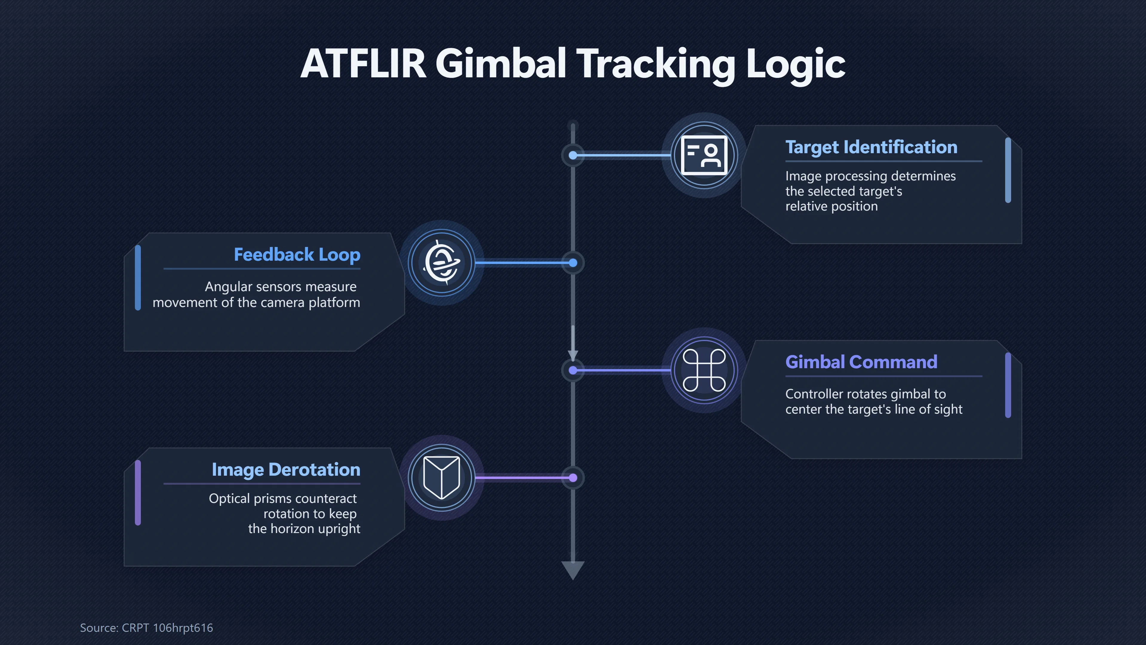
A tracking gimbal operates as a feedback system. Image processing determines where the selected target lies relative to the desired aim point, while angular sensors and stabilisation hardware measure or compensate for movement of the camera platform. The controller then commands the gimbal to rotate until the camera’s optical axis again points towards the target. An experimental three-axis airborne tracking system described in Applied Sciences, for example, switches into a tracking mode that keeps the target in the centre of the camera view; its tracking loop commands the camera boresight towards the target’s line of sight while a separate stabilising loop compensates for motion and disturbances from the aircraft.[MDPI]mdpi.comReal-Time Visual Tracking of Moving Targets Using a Low-Cost Unmanned Aerial Vehicle with a 3-Axis Stabilized Gimbal SystemJuly 23, 2020…
This distinction between tracking and stabilisation matters. Stabilisation tries to prevent aircraft vibration, banking and other platform disturbances from knocking the view away from its commanded direction. Tracking deliberately changes that commanded direction as the target’s apparent position changes. Engineering literature on electro-optical tracking systems similarly describes the gimbal as performing coarse target tracking and disturbance suppression, with additional steering hardware potentially providing finer corrections.[MDPI]mdpi.comA New Disturbance Feedforward Control Method for Electro-Optical Tracking System Line-Of-Sight Stabilization on Moving Platform…
Consequently, an object can remain almost motionless in image coordinates while the physical camera is continually rotating relative to the aircraft. Suppose a distant object would naturally drift ten degrees to the right across the detector because the aircraft is flying past it. An automatic tracker can instead rotate the line of sight those ten degrees towards the object. The resulting video no longer displays the object’s full angular drift. The movement has effectively been transferred into the gimbal’s pointing history.
That is not a camera failure. It is what successful tracking looks like.
This is particularly relevant to military infrared UFO footage because ATFLIR was built as a tracking sensor rather than an ordinary video camera. A US congressional report describing the system states that the pod detects, classifies and tracks targets and specifically discusses its automatic-track capability.[GovInfo]govinfo.govCRPT 106hrpt616SPENCE NATIONAL DEFENSE…… (ATFLIR) pods for both Navy and Marine Corps F/A-18C/D aircraft, and $23.8… automatic track at required… The publicly released Navy ‘Gimbal’ recording is identified by the All-domain Anomaly Resolution Office (AARO) as footage from an F/A-18 encounter and remains officially listed as unresolved.[AARO]aaro.milUAP ImageryUAP Case Resolution Reports · UAP Reporting Trends · UAP Records… NAVAIR - FOIA: Unresolved Case: Gimbal Video, NAVAIR…
Why camera rotation can disappear from the picture
The counter-intuitive part is that a rotating camera does not necessarily produce a visibly rotating recording.
A simple handheld camera makes its orientation obvious: rotate the camera clockwise and the horizon rotates anticlockwise in the frame. Sophisticated airborne sensors cannot always leave the image like that. Their gimbals may need to change orientation dramatically while following targets, so optical or electronic systems can compensate for unwanted image rotation and present the operator with a more usable view.
This is not speculative technology inferred from UFO videos. Patents for airborne infrared targeting systems describe it directly. One Raytheon-assigned targeting-system patent describes a roll gimbal together with a ‘deroll’ assembly providing image-roll and horizontal stabilisation. It states that the infrared image is derolled using a rotating prism, counteracting image rotation produced as parts of the gimbal system move.[Google Patents]patents.google.comGoogle PatentsUS6359681B1 - Combined laser/FLIR optics system - Google PatentsMarch 19, 2002…
Another patent explicitly identifies an exemplary implementation as an improvement to an ATFLIR pod. Its optical path includes a reflective derotation mechanism whose purpose is to keep the infrared image erect. The same document describes an outer roll gimbal that can rotate relative to the pod’s fixed structure.[Google Patents]patents.google.comGoogle PatentsEP1394494B1 - Precision optical alignment system - Google Patents… A component manufacturer’s technical catalogue likewise states that ATFLIR uses a slip ring allowing continuous rotation on its roll axis.[A2V]a2v.frMoog Components Group Slip Ring CatalogMoog Components Group Slip Ring CatalogMarch 3, 2015 — Infrared (ATFLIR), utilizes a Moog slip ring to allow continuous rotation in th…
The important point is not that every internal movement of every ATFLIR configuration is publicly documented. It is that the intuitive rule — ‘if the camera rotated, the whole video would obviously rotate’ — is unsafe. Airborne targeting optics can physically rotate their line of sight while compensating for some of the resulting image rotation before the operator ever sees the picture.
A useful way to think about the process is as three different coordinate systems:
- The aircraft moves and changes attitude. Its direction of travel and bank angle need not match the camera’s viewing direction.
- The gimbal moves relative to the aircraft. Target tracking continually changes the sensor’s line of sight.
- The displayed image may be stabilised or derotated. Optical or electronic processing can remove rotation that would otherwise reveal some of the gimbal’s movement.
The final video is therefore not a transparent record of the sensor’s physical orientation. It is the output of a controlled imaging system.
Why the background can look faster than the target
Once target lock has suppressed the target’s motion within the frame, the background becomes visually dominant.
Imagine an aircraft flying rapidly past a comparatively slow object. Without tracking, both object and landscape change position on screen. With target lock, however, the gimbal rotates so that the object stays close to the centre. The Earth’s surface, cloud layer or sea is not being tracked, so it sweeps through the changing field of view instead.
The viewer consequently sees a peculiar inversion: the object apparently sits still while the world races behind it. Human visual intuition tends to treat the centred object as the stable reference, even though the tracking system has deliberately made it stable.
This can combine with motion parallax. AARO’s reconstruction of the 2013 Aguadilla infrared UAP recording is useful because it demonstrates how large the discrepancy between apparent and reconstructed motion can become in an airborne sensor. AARO calculated that the objects were moving at roughly 3.6 metres per second, about 8 mph, while their apparently rapid motion resulted from motion parallax involving the aircraft’s speed, sensor zoom and changing geometry between observer, objects and background.[AARO]aaro.milPuerto Rico UAP Case ResolutionPuerto Rico UAP Case Resolution
Target lock adds another reason not to read screen motion literally. If the tracker is continually changing the viewing direction, background displacement contains information about camera motion as well as scene geometry. Measuring how rapidly terrain crosses the frame and attributing all of that angular motion to the centred object can therefore produce a seriously misleading speed estimate.
This is why the target’s location on the detector is not enough. Investigators ideally need aircraft position and attitude, gimbal azimuth and elevation or equivalent line-of-sight information, field of view, zoom state, target range and timing. Without those quantities, multiple real-world trajectories can potentially produce similar image sequences.

Gimbal shows why rotation is especially deceptive
The Navy’s 2015 ‘Gimbal’ video illustrates the issue particularly well because the object not only remains tracked but appears to rotate near the end of the released clip. AARO continues to categorise the case as unresolved, so there is no official finding establishing exactly what the object was or whether its apparent rotation was entirely instrumental.[AARO]aaro.milUAP ImageryUAP Case Resolution Reports · UAP Reporting Trends · UAP Records… NAVAIR - FOIA: Unresolved Case: Gimbal Video, NAVAIR…
Nevertheless, the footage has generated a technically important dispute: how much of the visible rotation belongs to the observed object, and how much might arise from the imaging system?
One proposed explanation is that the sensor’s changing orientation and image-derotation optics can make infrared glare or other camera-relative features appear to rotate while much of the background remains stabilised. The hardware evidence establishes the underlying possibility: ATFLIR-related designs contain rotating gimbal structures and mechanisms explicitly intended to derotate the infrared image.[Google Patents]patents.google.comGoogle PatentsUS6359681B1 - Combined laser/FLIR optics system - Google PatentsMarch 19, 2002… That makes sensor rotation a mechanism that has to be tested rather than dismissed merely because the displayed horizon does not execute an equally conspicuous turn.
But the case should not be presented as settled by that mechanism alone. Peings and von Rennenkampff’s reconstruction of possible Gimbal trajectories reaches a different interpretation. Their analysis uses the recorded line-of-sight information and reported range estimates to argue that some possible trajectories are consistent with unusual motion described by the aircrew, while also discussing the competing hypothesis that the infrared image represents glare from a conventional aircraft viewed at considerably greater range.[arXiv]arxiv.orgOpen source on arxiv.org.
That disagreement is useful because it exposes the central evidential problem. A video can establish the direction in which a tracking sensor was looking much more readily than it establishes the target’s three-dimensional trajectory. Range is particularly consequential. The same changing line of sight can correspond to very different physical paths depending on how far away the object actually was.
Target lock therefore does not prove a mundane explanation for Gimbal, or for another UAP recording. It removes a much simpler assumption: that the apparent orientation and movement visible in a stabilised display can automatically be treated as the object’s unprocessed motion.
Clues that reveal active target lock
Even when camera movement has been visually suppressed, several features can warn an analyst that the recording is being actively tracked rather than produced by a fixed camera.
The target remains unusually well centred. A moving aircraft, atmospheric disturbance and an independently moving object would normally produce considerable image drift. Persistent centring is itself evidence that a control loop may be correcting the line of sight. Tracking-system research explicitly describes the goal as keeping pointing error near zero and holding the target at the centre of the field of view.[MDPI]mdpi.comReal-Time Visual Tracking of Moving Targets Using a Low-Cost Unmanned Aerial Vehicle with a 3-Axis Stabilized Gimbal SystemJuly 23, 2020…
The background moves while the target hardly does. This does not by itself establish high target speed. It is exactly the pattern expected when a tracker follows one angular direction while the aircraft continues along its own trajectory.
The viewing angle changes even though the composition looks stable. Sensor telemetry is especially valuable here. If azimuth, elevation or line-of-sight indicators change while the target stays centred, the display is directly signalling that the camera is steering to maintain the observation.
Sudden image adjustments can coincide with changing geometry. Gimballed systems have mechanical and control constraints, and different axes can interact as the viewing direction changes. Engineering work on airborne gimbals explicitly accounts for cross-coupling between roll, elevation and azimuth channels.[MDPI]mdpi.comReal-Time Visual Tracking of Moving Targets Using a Low-Cost Unmanned Aerial Vehicle with a 3-Axis Stabilized Gimbal SystemJuly 23, 2020… A brief image shift or rotation therefore deserves comparison with gimbal geometry before it is interpreted as an abrupt manoeuvre by the target.
A stable horizon is not decisive evidence against sensor rotation. Image derotation exists specifically to compensate for rotations produced within an airborne optical system. Patented systems describe optical prisms, reflective mechanisms or other means of counter-rotating the image so that its orientation remains useful despite movement of the sensor.[Google Patents]patents.google.comGoogle PatentsUS6359681B1 - Combined laser/FLIR optics system - Google PatentsMarch 19, 2002…
None of these clues individually identifies the object. Together, however, they tell an analyst that raw visual intuition is inadequate.
The key distinction: image coordinates versus real motion
Target lock changes the question that should be asked of UFO footage. Instead of asking, ‘How fast does this object look as though it is moving across the background?’, the useful question is, ‘What combination of aircraft movement, gimbal rotation, stabilisation, target range and target motion would produce these pixels?’
That distinction is fundamental because a tracked video records relative angular geometry, not an independent measurement of target velocity. The control system is deliberately manipulating the camera’s orientation so that the target occupies approximately the same image coordinates from frame to frame. Research into inertially stabilised platforms treats line-of-sight stabilisation and target tracking as coupled control problems for exactly this reason.[arXiv]arxiv.orgOpen source on arxiv.org.
The strongest analysis therefore comes from reconstructing the observation geometry rather than treating the displayed frame as though it came from a stationary tripod. Aircraft navigation data can establish how the observer moved. Sensor angles can establish where the camera was looking. Field of view determines the conversion between pixels and angular displacement. Range information, where available, converts those angular measurements into physical distances and speeds.
Without that reconstruction, target lock can conceal the very camera rotation needed to interpret the recording correctly. A UFO may appear almost motionless while the landscape streams past it; an apparently level scene may conceal substantial movement of the sensor assembly; and apparent changes in orientation may require examination of image derotation and optical effects before they can confidently be assigned to the object.
The appropriate conclusion is therefore limited but important. Target lock does not explain every UFO or UAP recording, nor does it establish that a particular target was stationary or conventional. It demonstrates why stabilised airborne footage cannot be read like ordinary video. When the camera is actively following the object, some of the motion that seems to belong to the UFO may actually be encoded in the hidden movement of the camera itself.
Amazon book picks
Further Reading
Books and field guides related to When Target Lock Makes the Background Look Fast. Use these as the next step if you want deeper reading beyond the article.
Computer Vision: Algorithms and Applications
Computer Vision: Algorithms and Applications explores the variety of techniques used to analyze and interpret images. It also describes c...
Modern Control Engineering
Rating: 4.0/5 from 8 Google Books ratings
Mathematical modeling of control systems. Mathematical modeling of mechanical systems and electrical systems. Mathematical modeling of fl...
Feedback Control of Dynamic Systems
Emphasizing modern topics and techniques, this text blends theory and real world practice, mixes design and analysis, introduces design e...
Multiple View Geometry in Computer Vision
A basic problem in computer vision is to understand the structure of a real world scene given several images of it. Techniques for solvin...
eBay marketplace picks
Marketplace Samples
Live-tested eBay searches with available results related to this page.
Selected fromUFO poster oneBay.co.uk.

Current eBay listing
I Want To Believe UFO Poster Giclée Fine Art Heavyweight Print


Current eBay listing
VINTAGE UFO FLYING SAUCERS COMIC ADVERTISING A2 POSTER PRINT

Endnotes
1.
Source: mdpi.com
Link:https://www.mdpi.com/2076-3417/10/15/5064
Source snippet
Real-Time Visual Tracking of Moving Targets Using a Low-Cost Unmanned Aerial Vehicle with a 3-Axis Stabilized Gimbal SystemJuly 23, 2020...
Published: July 23, 2020
2.
Source: mdpi.com
Link:https://www.mdpi.com/1424-8220/18/12/4350
Source snippet
A New Disturbance Feedforward Control Method for Electro-Optical Tracking System Line-Of-Sight Stabilization on [Moving Platform]({{ 'moving-platform/' | relative_url }})...
3.
Source: patents.google.com
Link:https://patents.google.com/patent/US6359681B1/en
Source snippet
Google PatentsUS6359681B1 - Combined laser/FLIR optics system - Google PatentsMarch 19, 2002...
Published: March 19, 2002
4.
Source: patents.google.com
Link:https://patents.google.com/patent/EP1394494B1/en
Source snippet
Google PatentsEP1394494B1 - Precision optical alignment system - Google Patents...
5.
Source: govinfo.gov
Title: CRPT 106hrpt616
Link:https://www.govinfo.gov/content/pkg/CRPT-106hrpt616/html/CRPT-106hrpt616.htm
Source snippet
SPENCE NATIONAL DEFENSE...... (ATFLIR) pods for both Navy and Marine Corps F/A-18C/D aircraft, and $23.8... automatic track at required...
6.
Source: aaro.mil
Link:https://www.aaro.mil/UAP-Cases/Official-UAP-Imagery/
Source snippet
UAP ImageryUAP Case Resolution Reports · UAP Reporting Trends · UAP Records... NAVAIR - FOIA: Unresolved Case: Gimbal Video, NAVAIR...
7.
Source: a2v.fr
Title: Moog Components Group Slip Ring Catalog
Link:https://www.a2v.fr/moog/doc/catalogue-complet-moog-anglais.pdf
Source snippet
Moog Components Group Slip Ring CatalogMarch 3, 2015 — Infrared (ATFLIR), utilizes a Moog slip ring to allow continuous rotation in th...
Published: March 3, 2015
8.
Source: aaro.mil
Title: [Puerto Rico]({{ ‘puerto-rico/’ | relative_url }}) UAP Case Resolution
Link:https://www.aaro.mil/Portals/136/PDFs/case_resolution_reports/AARO_Puerto_Rico_UAP_Case_Resolution.pdf
9.
Source: arxiv.org
Link:https://arxiv.org/abs/2306.08773
10.
Source: patents.google.com
Link:https://patents.google.com/patent/WO2015012902A1/en
11.
Source: arxiv.org
Link:https://arxiv.org/abs/2311.01859
12.
Source: arxiv.org
Link:https://arxiv.org/abs/1602.06832
13.
Source: aaro.mil
Link:https://www.aaro.mil/Next-AARO-Home-redesign/Next-Parent/Next-UAP-Report-Documents/poster/dividLink/
14.
Source: aaro.mil
Link:https://www.aaro.mil/Next-AARO-Home-redesign/Next-Parent/Next-AARO-UAP-Imagery-Acc-Table/
15.
Source: aaro.mil
Link:https://www.aaro.mil/Next-AARO-Home-redesign/Next-Parent/Presidential-UAP-Transparency-Initiative/dvpmoduleid/77396/
16.
Source: mdpi.com
Link:https://www.mdpi.com/2076-0825/14/5/240
17.
Source: aaro.mil
Link:https://www.aaro.mil/Next-AARO-Home-redesign/Next-Parent/Presidential-UAP-Transparency-Initiative/videoid/1006080/dvpmoduleid/77396/
18.
Source: aaro.mil
Link:https://www.aaro.mil/Next-AARO-Home-redesign/Next-Parent/Presidential-UAP-Transparency-Initiative/videoid/1007707/dvpcc/false/
19.
Source: aaro.mil
Link:https://www.aaro.mil/Next-AARO-Home-redesign/Next-Parent/Presidential-UAP-Transparency-Initiative/videoid/1006105/dvpmoduleid/77396/
20.
Source: patents.google.com
Link:https://patents.google.com/patent/US10375311B2/en
21.
Source: patents.google.com
Link:https://patents.google.com/patent/US6737664B2/de
22.
Source: patents.google.com
Link:https://patents.google.com/patent/US6359681B1/xx
23.
Source: patents.google.com
Link:https://patents.google.com/patent/US6020955A/en
24.
Source: patents.google.com
Link:https://patents.google.com/patent/US6020955A
25.
Source: aaro.mil
Link:https://www.aaro.mil/UAP-Cases/Official-UAP-Imagery/4/
26.
Source: aaro.mil
Link:https://www.aaro.mil/Next-AARO-Home-redesign/Next-Parent/Next-UAP-Case-RR-Data-Table/
27.
Source: aaro.mil
Link:https://www.aaro.mil/UAP-Cases/Official-UAP-Imagery/ftag/MSF0951a18/
28.
Source: aaro.mil
Link:https://www.aaro.mil/Next-AARO-Home-redesign/Next-Parent/AARO-UAP-Case-Resolution-DT/
29.
Source: aaro.mil
Title: UAP Imagery* “[Go Fast]({{ ‘go-fast/’ | relative_url }})” Object NAVAIR
Link:https://www.aaro.mil/Next-AARO-Home-redesign/Inactive-Parent/Next-UAP-Imagery-dup/
30.
Source: aaro.mil
Title: AAR O UAP Trends All-domain Anomaly Resolution Office UAP REPORTING TRENDS
Link:https://www.aaro.mil/UAP-Cases/UAP-Reporting-Trends/
31.
Source: aaro.mil
Link:https://www.aaro.mil/Next-AARO-Home-redesign/Inactive-Parent/FAQ-Datatable/
32.
Source: raytheon.com
Link:https://www.raytheon.com/rtx-gdpr/rtx-gdpr-overlay
33.
Source: patents.justia.com
Link:https://patents.justia.com/patent/20150028194
34.
Source: patents.justia.com
Link:https://patents.justia.com/patent/20120292482
35.
Source: signalsfromtheperiphery.com
Link:https://signalsfromtheperiphery.com/en/gimbal/
36.
Source: journals.tubitak.gov.tr
Link:https://journals.tubitak.gov.tr/elektrik/vol29/iss5/16/
Additional References
37.
Source: pmc.ncbi.nlm.nih.gov
Link:https://pmc.ncbi.nlm.nih.gov/articles/PMC6308726/
Source snippet
PubMed Central (PMC)A New Disturbance Feedforward Control Method for Electro-Optical Tracking System Line-Of-Sight Stabilization on Movin...
38.
Source: youtube.com
Title: GOFAST UFO Analysis (yeah no, probably just a balloon)
Link:https://www.youtube.com/watch?v=-3NYowlCoDc
Source snippet
Raytheon ATFLIR expert discusses Navy gimbal UFO/UAP video with Mick West...
39.
Source: oig.nasa.gov
Link:https://oig.nasa.gov/audits/nasas-management-of-programs-and-projects-after-mission-termination-canceled-or-repurposed-artemis-campaign-systems/
40.
Source: youtube.com
Title: The SHOCKING Math Error Behind Viral UFO Videos | Mick West
Link:https://www.youtube.com/watch?v=ypfbhfEXnBo
Source snippet
GOFAST UFO Analysis (yeah no, probably just a balloon)...
41.
Source: science.nasa.gov
Title: improved hubble yardstick gives fresh evidence for new physics in the universe
Link:https://science.nasa.gov/missions/hubble/improved-hubble-yardstick-gives-fresh-evidence-for-new-physics-in-the-universe/
42.
Source: researchgate.net
Link:https://www.researchgate.net/publication/329540513_A_New_Disturbance_Feedforward_Control_Method_for_Electro-Optical_Tracking_System_Line-Of-Sight_Stabilization_on_Moving_Platform
43.
Source: researchgate.net
Link:https://www.researchgate.net/publication/245433920_Fast_Model_Predictive_Control_of_the_Nadir_Singularity_in_Electro-Optic_Systems?_tp=eyJjb250ZXh0Ijp7InBhZ2UiOiJzY2llbnRpZmljQ29udHJpYnV0aW9ucyIsInByZXZpb3VzUGFnZSI6bnVsbCwic3ViUGFnZSI6bnVsbH19
44.
Source: rtx.com
Link:https://www.rtx.com/raytheon/what-we-do/land/flir
45.
Source: rtx.com
Link:https://www.rtx.com/raytheon/what-we-do/air/apg79aesa
46.
Source: rtx.com
Link:https://www.rtx.com/raytheon/what-we-do/sea/aim-9x-sidewinder-missile